Introduction
A motor with one Dahlander or tapped winding and a separate low speed winding will give the motor three speeds, possible pole configurations are for the Dahlander winding 8/4 or 4/2 poles and for the low speed winding 12 or 8 poles. For 50Hz supplies this would give speeds of 750/1500 or 1500/3000rpm for the Dahlander winding and 500 or 750rpm for the high speed winding. For 60Hz supplies this equates to 900/1800 or 1800/3600rpm and 600 or 900rpm respectively.
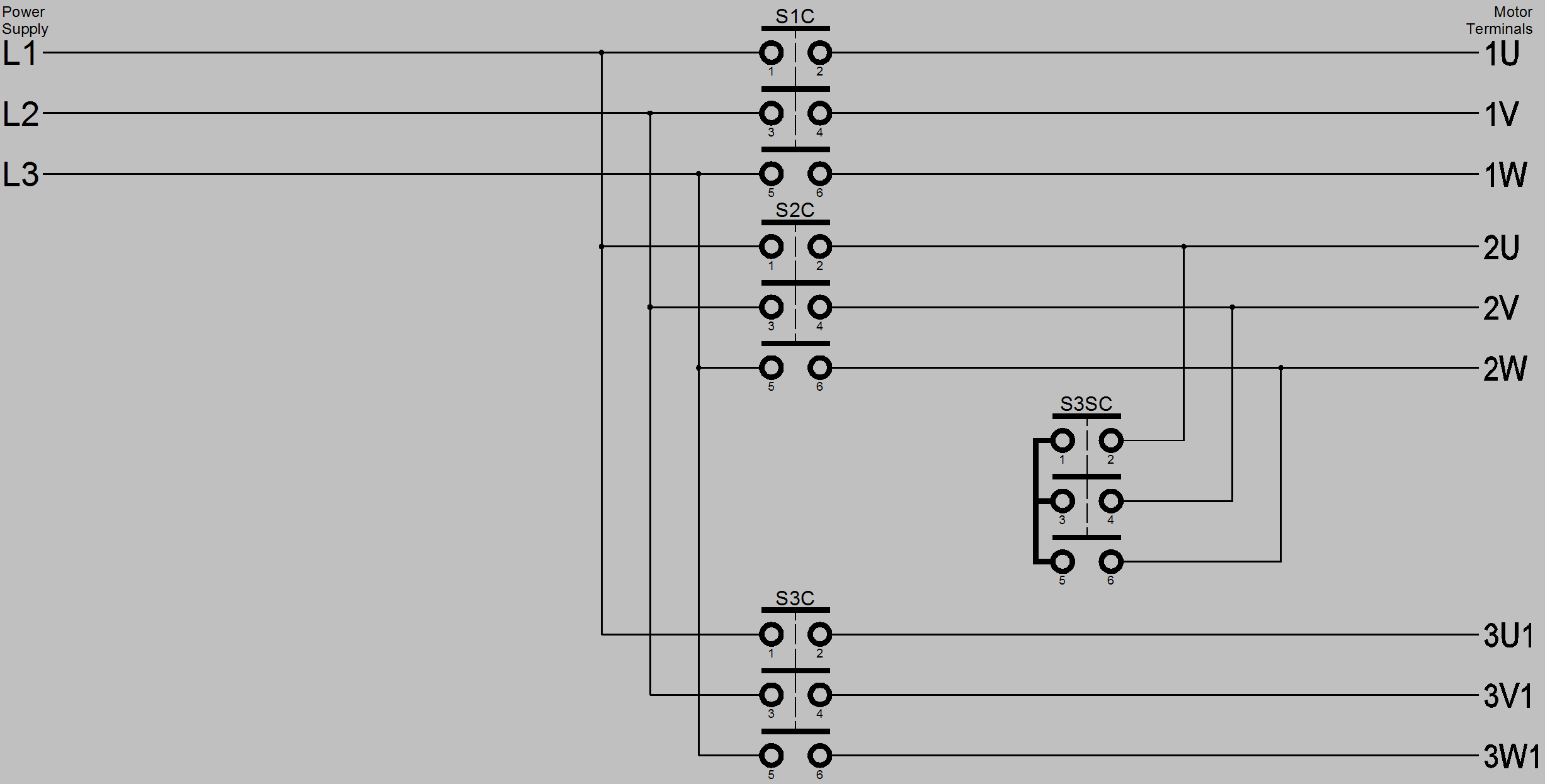
Power Circuit
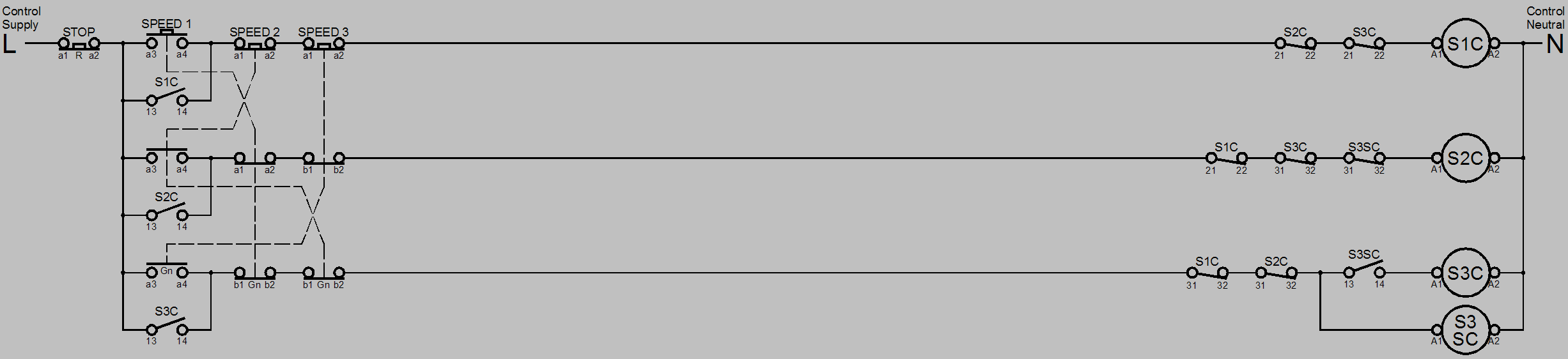
Control Circuit (where direct on line starting at any speed is permitted)
Circuit Operation
As direct on line starting for any speed has been determined for this motor it follows that if the motor is at standstill and speed 1, speed 2 or speed 3 is selected the motor will start at the selected speed and run up to full speed in that speed.
When the motor is at standstill and the speed 1 start button is pressed it’s contacts a3-a4 close and a1-a2, b1-b2 open.
The speed 1 push button contact on terminals a3-a4 closes to energise the speed 1 contactor S1C which causes it’s main contacts on terminals 1-2, 3-4 and 5-6 to close, it’s normally open auxiliary contacts 13-14 close and normally closed auxiliary contacts 21-22, 31-32 open, the normally open contact on terminals 13-14 closes to maintain power to the speed 1 contactor when the button is released. Power is connected from the power supply to the motor terminals 1U, 1V and 1W. The motor starts and accelerates to full speed in speed 1.
When the motor is at standstill and the speed 2 start button is pressed it’s contacts a3-a4 close and a1-a2, b1-b2 open.
The speed 2 push button contact on terminals a3-a4 closes to energise the speed 2 contactor S2C which causes it’s main contacts on terminals 1-2, 3-4 and 5-6 to close, it’s normally open auxiliary contacts 13-14 close and normally closed auxiliary contacts 21-22, 31-32 open, the normally open contact on terminals 13-14 closes to maintain power to the speed 2 contactor when the button is released. Power is connected from the power supply to the motor terminals 2U, 2V and 2W. The motor starts and accelerates to full speed in speed 2.
When the motor is at standstill and the speed 3 start button is pressed it’s contacts a3-a4 close and a1-a2, b1-b2 open.
The speed 3 push button contact on terminals a3-a4 closes to energise the speed 3 star contactor S3SC which causes it’s main contacts on terminals 1-2, 3-4 and 5-6 to close and it’s normally open auxiliary contact on terminals 13-14 to close Terminals 2U, 2V and 2W are short circuited which changes the Dahlander winding’s number of poles, when the normally open auxiliary contact on terminals 13-14 of the speed 3 star contactor close it energises the speed 3 contactor S3C which causes it’s main contacts on terminals 1-2, 3-4 and 5-6 to close, it’s normally open auxiliary contact on terminals 13-14 to close and normally closed auxiliary contacts 21-22, 31-32 open. The normally open contact on terminals 13-14 closes to maintain power to the speed 3 contactor when the button is released. Power is connected from the power supply to the motor terminals 3U1, 3V1 and 3W1. The motor now accelerates to full speed in speed 3.
To change speed whilst the motor is running it is only necessary to press the appropriate button which will cause the energised contactor or contactors to de-energise and the selected speed contactor or contactors to energise.
To stop the motor the stop button is pressed its contact a1-a2 opens which de-energises all the energised contactors thus stopping the motor by removing its power supply and resetting the control circuits.
The auxiliary normally closed contacts on terminals 21-22 and 31-32 of the speed 1 S1C, speed 2 S2C and speed 3 S3C contactors are placed into each others coil circuit so that electrically only one contactor can be energised at a time, if two or more were simultaneously energised it would cause an overload or short circuit in the windings, this can be seen by examination of the above circuit. It is normal to mechanically interlock the speed 2 and speed 3 contactors in addition to the electrical interlock. It is not possible with most contactors to mechanically interlock with two other contactors where this is possible all three speed contactors should be mechanically interlocked.
The auxiliary normally closed contacts on terminals 21-22 of the speed 1 S2C and speed 3 star S3SC contactors are placed into each others coil circuit so that electrically the two contactors cannot be simultaneously energised which would cause a short circuit, this can be seen by examination of the above circuit. However it is normal to mechanically interlock the speed 2 and speed 3 star contactors in addition to the electrical interlock.
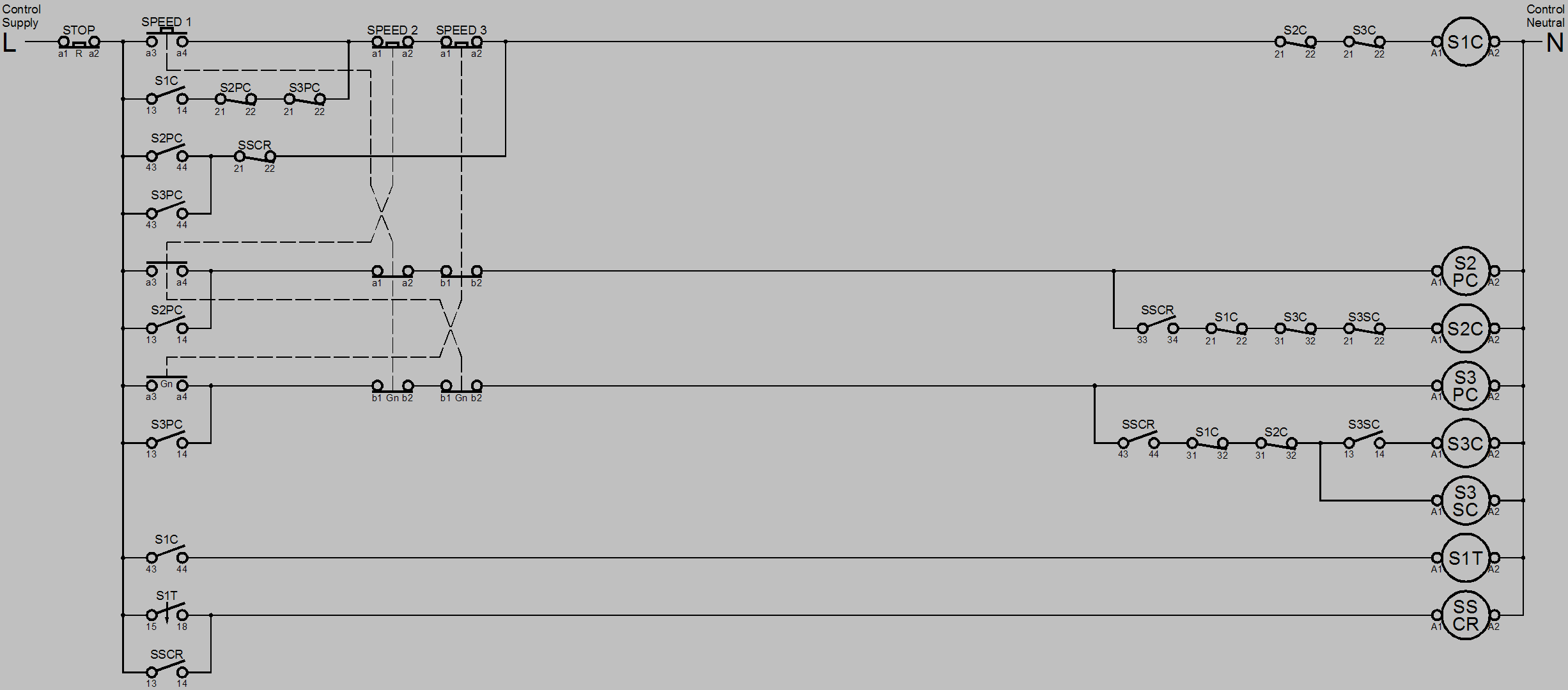
Control Circuit (where direct on line starting at low speed only is permitted)
Circuit Operation
As direct on line starting is permitted only for speed 1 of this motor it follows that if the motor is at standstill and either speed 2 or speed 3 is selected the motor will start at speed 1 and accelerate to full speed in speed 1 then switch over to the selected speed.
This is achieved by adding a pilot contactor to the speed 2 and speed 3 contactor circuits and a start sequence complete relay.
When the motor is at standstill and the speed 1 start button is pressed it’s contacts a3-a4 close and a1-a2, b1-b2 open.
The speed 1 push button contact on terminals a3-a4 closes to energise the speed 1 contactor S1C which causes it’s main contacts on terminals 1-2, 3-4 and 5-6 to close, it’s normally open auxiliary contacts on terminals 13-14 close and normally closed auxiliary contact on terminals 21-22, 31-32 open, the normally open contact on terminals 13-14 closes to maintain power to the speed 1 contactor when the button is released. Power is connected from the power supply to the motor terminals 1U, 1V and 1W. The motor is connected to the full line voltage and accelerates to full speed in speed 1.
When the speed 1 contactor S1C energises it’s auxiliary normally open contact on terminals 43-44 closes, which starts the timing sequence of speed 1 timer S1T when that timer times out it’s contact on terminals 15-18 close which energises the start sequence complete relay SSCR. When the start sequence complete relay energises the normally open contact on terminals 13-14 closes to keep the relay energised.
The purpose of the start sequence complete relay SSCR is to facilitate switching between the speeds without having to go through the speed 1 starting sequence; it is de-energised when the stop button is pressed.
When the motor is at standstill and the speed 2 start button is pressed it’s contacts a3-a4 close and a1-a2, b1-b2 open.
The speed 2 push button contact on terminals a3-a4 closes to energise the speed 2 pilot contactor S2PC it’s contacts on terminals 13-14, 43-44 close and 21-22 open, the normally open contact on terminals 13-14 closes to maintain power to the speed 2 pilot contactor S2PC when the button is released, the closing of the normally open contact on terminals 43-44 initiates the speed 1 starting circuit which operates as detailed above, whilst the normally closed contact on terminals 21-22 opens to prevent the speed 1 contactor S1C maintaining circuit from keeping the speed 1 contactor energised.
At the completion of the speed 1 starting sequence the starting sequence complete relay SSCR energises the normally open contact on terminals 13-14 closes to keep the relay energised a normally closed contact on terminals 21-22 opens which de-energises the speed 1 contactor and a normally open contact on terminals 33-34 closes to complete the circuit to the speed 2 contactor coil S2C energises which causes it’s main contacts on terminals 1-2, 3-4 and 5-6 to close, it’s normally closed auxiliary contacts 21-22, 31-32 open. Power is connected from the power supply to the motor terminals 2U, 2V and 2W. The motor now accelerates to full speed in speed 2.
When the motor is at standstill and the speed 3 start button is pressed it’s contacts a3-a4 close and a1-a2, b1-b2 open.
The speed 3 push button contact on terminals a3-a4 closes to energise the speed 3 pilot contactor S3PC it’s contacts on terminals 13-14, 43-44 close and 21-22 open, the normally open contact on terminals 13-14 closes to maintain power to the speed 3 pilot contactor S3PC when the button is released, the closing of the normally open contact on terminals 43-44 initiates the speed 1 starting circuit which operates as detailed above, whilst the normally closed contact on terminals 21-22 opens to prevent the speed 1 contactor S1C maintaining circuit from keeping the speed 1 contactor energised.
At the completion of the speed 1 starting sequence the starting sequence complete relay SSCR energises the normally open contact on terminals 13-14 closes to keep the relay energised a normally closed contact on terminals 21-22 opens which de-energises the speed 1 contactor and a normally open contact on terminals 43-44 closes to complete the circuit to the speed 3 star contactor coil S3SC which energises causing it’s main contacts on terminals 1-2, 3-4 and 5-6 to close and it’s normally open auxiliary contact on terminals 13-14 to close Terminals 2U, 2V and 2W are short circuited which changes the Dahlander winding’s number of poles, when the normally open auxiliary contact on terminals 13-14 of the speed 3 star contactor closes it energises the speed 3 contactor S3C which causes it’s main contacts on terminals 1-2, 3-4 and 5-6 to close, it’s normally closed auxiliary contacts 21-22, 31-32 open. Power is connected from the power supply to the motor terminals 3U1, 3V1 and 3W1. The motor now accelerates to full speed in speed 3.
To change speed whilst the motor is running it is only necessary to press the appropriate button which will cause the energised contactor or contactors to de-energise and the selected speed contactor or contactors to energise. Where that speed change is from speed 2 to speed 1 the motor is connected in ‘run’ without going through the starting sequence.
To stop the motor the stop button is pressed its contact a1-a2 opens which de-energises all the energised contactors, relays and timers thus stopping the motor by removing its power supply and resetting the control circuits.
The auxiliary normally closed contacts on terminals 21-22 and 31-32 of the speed 1 S1C, speed 2 S2C and speed 3 S3C contactors are placed into each others coil circuit so that electrically only one contactor can be energised at a time, if two or more were simultaneously energised it would cause an overload or short circuit in the windings, this can be seen by examination of the above circuit. It is normal to mechanically interlock the speed 2 and speed 3 contactors in addition to the electrical interlock. It is not possible with most contactors to mechanically interlock with two other contactors where this is possible all three speed contactors should be mechanically interlocked.
The auxiliary normally closed contacts on terminals 21-22 of the speed 1 S2C and speed 3 star S3SC contactors are placed into each others coil circuit so that electrically the two contactors cannot be simultaneously energised which would cause a short circuit, this can be seen by examination of the above circuit. However it is normal to mechanically interlock the speed 2 and speed 3 star contactors in addition to the electrical interlock.